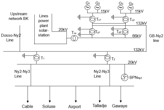
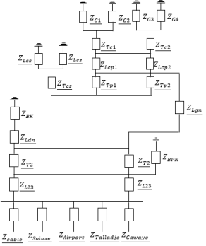
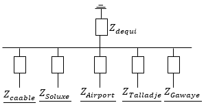
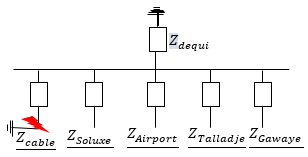
Most faults in power lines are caused by short circuits resulting from phenomena such as lightning, severe weather, or power surges linked to circuit breaker operations. These short circuits, whether temporary or permanent, require accurate detection and location to enable rapid repair and restoration of power supply. To protect the system against short-circuit currents, which can cause irreversible damage to key equipment, it is essential to quickly disconnect the faulty part of the network. In order to correctly size this equipment, it is essential to estimate the magnitude of the currents likely to flow during a short circuit. This study involved calculating single-phase short-circuit currents in the event of a fault on the Cable, Soluxe, Airoport, Talladje, and Gawaye feeders at the Niamey3 electrical substation. The method used to calculate short-circuit currents in HTB and HTA networks is based on the principle of symmetrical components. This method was chosen for its accuracy and analytical nature. The results obtained show that the Soluxe feeder has the highest short-circuit current, with a value of 1.95 kA, compared to those of the Cable, Airoport, Talladje, and Gawaye feeders, which are 1.86 kA, 0.67 kA, 0.64 kA, and 0.56 kA, respectively. This is explained by the fact that the calculated impedances (direct, inverse, and zero-sequence) of this feeder are lower than those of the other four feeders.
| Published in | International Journal of Energy and Power Engineering (Volume 14, Issue 6) |
| DOI | 10.11648/j.ijepe.20251406.11 |
| Page(s) | 142-150 |
| Creative Commons |
This is an Open Access article, distributed under the terms of the Creative Commons Attribution 4.0 International License (http://creativecommons.org/licenses/by/4.0/), which permits unrestricted use, distribution and reproduction in any medium or format, provided the original work is properly cited. |
| Copyright |
Copyright © The Author(s), 2025. Published by Science Publishing Group |
Nature | Almelec | Copper | Aluminum |
|---|---|---|---|
|
|
|
|
Power (MVA) | Voltage (kV) | Voltage Ucc (%) | Coupling | |
|---|---|---|---|---|
Upstream network seen from Dosso (BK) | 400 | 132 | ||
Niamey 2 transformer (T1 and T2) | 40 | 132/20 | 9,02 | YNd11 |
Gorou Banda group (GB) | 26,45 | 11 | ||
GB central transformer (Tc) | 53 | 11/132 | 13 | YNd11 |
GB substation transformer (Tp) | 63 | 132/66 | 11,2 | YNyn0 |
GB20 substation transformer (Ts) | 30 | 66/20 | 6 | YNd11 |
Voltage (kV) | Lengh (km) | Section/phase (mm²) | Network Type | Nature of the conductor | |
|---|---|---|---|---|---|
Dosso-Niamey2 line (Ldn) | 132 | 132 | 242 | Aerial | Almelec |
Niamey 2- Niamey 3 line (L23) | 20 | 0,32 | 2630 | Underground | Aluminum |
Centrale - Gorou Banda station line (Lcp) | 132 | 1 | 2291 | Aerial | Almelec |
Gorou Banda station -Niamey 2 line (Lpn) | 132 | 10 | 2291 | Aerial | Almelec |
Solar power line - station (Lcs) | 20 | 1 | 2630 | Underground | Aluminum |
Un (kV) | ||
|---|---|---|
BPNNy2 | 26,5 | 20 |
HTA departures | SECTION (mm²) | Length (km) | Type of conductor | |
|---|---|---|---|---|
Câble | Underground | 240 | 7,287 | Aluminum |
Soluxe | Underground | 240 | 6,502 | Aluminum |
Aéroport | Overhead | 75,5 | 7,730 | Almelec |
54,6 | 4,059 | Almelec | ||
54,6 | 0,296 | Copper | ||
Underground | 240 | 3,552 | Aluminum | |
150 | 0,049 | Aluminum | ||
Talladje | Overhead | 75,5 | 11,616 | Almelec |
54,6 | 8,292 | Almelec | ||
240 | 4,544 | Aluminum | ||
Gawaye | Underground Overhead | 75,5 | 4,273 | Almelec |
54,6 | 2,623 | Almelec | ||
Underground | 240 | 7,804 | Aluminum | |
150 | 0,067 | Aluminum | ||
Network components | R | X |
|
|---|---|---|---|
Upstream network (BK) | 0 | 9,59 | j9,59 |
Dosso-Ny2 line (Ldn) | 18 | 52,8 | 18+j52,8 |
Niamey2 transformer (T2) | 0 | 39,29 | j39,29 |
Niamey2-Niamey3 line (L23) | 0,0075 | 0,016 | 0,0075+j0,016 |
Gorou Banda group (G) | 0 | 5,49 | j5,49 |
Gorou Banda central transformer (Tc) | 0 | 0,296 | j0,296 |
Central- Gorou Banda substation line (Lcp) | 0,11 | 0,4 | 0,11+j0,4 |
Gorou Banda substation transformer (Tp) | 0 | 31 | j31 |
Gorou Banda -Niamey2 line (Lgn) | 0.57 | 4 | 0.57+j4 |
Solar central line – Gorou Banda substation (Lcs) | 0,05 | 0,1 | 0,05+j0,1 |
Gorou Banda 20 transformer (Tcs) | 0 | 8,71 | j8,71 |
Departures | R | X |
|
|---|---|---|---|
Cable | 0,98 | 0,78 | 0,98+j0,78 |
Soluxe | 0,81 | 0,65 | 0,81+j0,65 |
Airport | 6,38 | 5,2 | 6,38+j5,2 |
Gawaye | 4,47 | 3,55 | 4,47+j3,55 |
Talladje | 10,65 | 8,42 | 10,65+j8,42 |
Network components | R | X |
|
|---|---|---|---|
Upstream network (BK) | 0 | 0,22 | j0,22 |
Dosso-Niamey2 line (Ldn) | 0,41 | 1,21 | 0,41+j1,21 |
Niamey2 transformer (T2) | 0 | 0,9 | j0,9 |
Niamey2-Niamey3 line (L23) | 0,0075 | 0,016 | 0,0075+j0,016 |
Gorou Banda group (G) | 0 | 18,15 | j18,15 |
Gorou Banda central transformer (Tc) | 0 | 0,98 | j0,98 |
Central-Gorou Banda substation line (Lcp) | 0,0026 | 0,0092 | 0,0026+j0,0092 |
Gorou Banda substation transformer (Tp) | 0 | 0,71 | j0,71 |
Gorou Banda-Ny2 line (Lgn) | 0,13 | 0,92 | 0,13+j0,92 |
Solar central line – GD substation (Lcs) | 0,05 | 0,1 | 0,05+j0,1 |
Gorou Banda 20 transformer (Tcs) | 0 | j0,8 | j0,8 |
Network components | R | X |
|
|---|---|---|---|
Upstream network (BK) | 0 | 2,4 | j2,4 |
Dosso-Ny2 line (Ldn) | 1,23 | 3,63 | 1,23+j3,63 |
Ny2 transformer (T2) | 0 | 0,9 | j0,9 |
Ny2-Ny3 line (L23) | 0,16 | 0,05 | 0,16+j0,05 |
Gorou Banda group (G) | 0 | 1,125 | j1,125 |
Gorou Banda central transformer (Tc) | 0 | 0,98 | j0,98 |
Central- Gorou Banda substation line (Lcp) | 0,15 | 0,003 | 0,15+j0,003 |
Gorou Banda substation transformer (Tp) | 0 | 0,71 | j0,71 |
Gorou Banda -Ny2 line (Lgn) | 0,075 | 0,276 | 0,075+j0,276 |
Solar central line – Gorou Banda substation (Lcs) | 0,2 | 0,3 | 0,2+j0,3 |
Gorou Banda 20 transformer (Tcs) | 0 | j0,8 | j0,8 |
Departures | R | X |
|
|---|---|---|---|
Cable | 2,94 | 2,34 | 2,94+j2,34 |
Soluxe | 2,43 | 1,95 | 2,43+j1,95 |
Airport | 19,14 | 15,6 | 19,14+j15,6 |
Gaweye | 13,41 | 10,65 | 13,41+j10,65 |
Talladje | 31,95 | 25,26 | 31,95+j25,26 |
Equivalent impedances | Cable | Soluxe | Airport | Talladje | Gawaye |
|---|---|---|---|---|---|
| 1,24 + j1,98 | 1,07+j1,85 | 6,64+j6,4 | 10,91+j9,62 | 4,73+j4,75 |
Equivalent impedances | Cable | Soluxe | Airport | Talladje | Gawaye |
|---|---|---|---|---|---|
| 3,32+j13,76 | 2,81+j13,32 | 19,52+j27,02 | 13,79+j22,07 | 32,33+j36,68 |
Short-circuit currents | Cable | Soluxe | Airport | Talladje | Gawaye |
|---|---|---|---|---|---|
ICC1(kA) | 1,86 | 1,95 | 0,67 | 0,64 | 0,56 |
Ω | Ohm |
A | Ampere |
B K | Birnin Kebbi |
GB | Gorou Banda |
Ny2 | Niamey 2 |
Ny3 | Niamey 3 |
R | Resistor |
X | Reactance |
Z | Impedance |
Zequi | Equivalent Impedance |
| [1] | Loiy Rashed Almobasher, Ibrahim Omar A Habiballah, Review of Power System Faults, International Journal of Engineering Research & Technology, 9, 61-64 (2020). |
| [2] | Neha Kumari, "Power System Faults: A Review," International Journal of Engineering Research & Technology (IJERT), 2016. |
| [3] | B. de Metz-Noblat, F. Dumas, C. Poulain, « Calculation of short-circuit currents », Cahier technique no. 158, updated September 2005. |
| [4] | BELBEY Mourad “Study and calculation of symmetrical and permanent three-phase short-circuit currents,” final thesis, Mouloud Mammeri University of Tizi-Ouzou, 2013/2014. |
| [5] | Bedel Giscard Onana Essama1 and al. “Electrical Network Influenced by overload, broken phase and short-circuit” ISAR Journal of Science and Technology, Vol-1, Iss-1 (Nov- 2023): 12-20. |
| [6] | Liu, L.; Li, X.; Teng, Y.; Luo, Y.; Chen, K. Improved Commutation Failure Prevention Control for Inter- Phase Short-Circuit Faults. Appl. Sci. 2025, 15, 9972. |
APA Style
Soumaïla, N. T., Nassirou, A. H. M., Moustapha, A. K. M., Moussa, I. I., Seibou, B. (2025). Study of Short-circuit Faults Affecting Electrical Networks. International Journal of Energy and Power Engineering, 14(6), 142-150. https://doi.org/10.11648/j.ijepe.20251406.11
ACS Style
Soumaïla, N. T.; Nassirou, A. H. M.; Moustapha, A. K. M.; Moussa, I. I.; Seibou, B. Study of Short-circuit Faults Affecting Electrical Networks. Int. J. Energy Power Eng. 2025, 14(6), 142-150. doi: 10.11648/j.ijepe.20251406.11
AMA Style
Soumaïla NT, Nassirou AHM, Moustapha AKM, Moussa II, Seibou B. Study of Short-circuit Faults Affecting Electrical Networks. Int J Energy Power Eng. 2025;14(6):142-150. doi: 10.11648/j.ijepe.20251406.11
@article{10.11648/j.ijepe.20251406.11,
  author = {Noma Talibi Soumaïla and Abdou Hamidine Mamane Nassirou and Attoumane Kosso Mamadou Moustapha and Insa Issoufou Moussa and Boureima Seibou},
  title = {Study of Short-circuit Faults Affecting Electrical Networks},
  journal = {International Journal of Energy and Power Engineering},
  volume = {14},
  number = {6},
  pages = {142-150},
  doi = {10.11648/j.ijepe.20251406.11},
  url = {https://doi.org/10.11648/j.ijepe.20251406.11},
  eprint = {https://article.sciencepublishinggroup.com/pdf/10.11648.j.ijepe.20251406.11},
  abstract = {Most faults in power lines are caused by short circuits resulting from phenomena such as lightning, severe weather, or power surges linked to circuit breaker operations. These short circuits, whether temporary or permanent, require accurate detection and location to enable rapid repair and restoration of power supply.  To protect the system against short-circuit currents, which can cause irreversible damage to key equipment, it is essential to quickly disconnect the faulty part of the network. In order to correctly size this equipment, it is essential to estimate the magnitude of the currents likely to flow during a short circuit. This study involved calculating single-phase short-circuit currents in the event of a fault on the Cable, Soluxe, Airoport, Talladje, and Gawaye feeders at the Niamey3 electrical substation. The method used to calculate short-circuit currents in HTB and HTA networks is based on the principle of symmetrical components. This method was chosen for its accuracy and analytical nature. The results obtained show that the Soluxe feeder has the highest short-circuit current, with a value of 1.95 kA, compared to those of the Cable, Airoport, Talladje, and Gawaye feeders, which are 1.86 kA, 0.67 kA, 0.64 kA, and 0.56 kA, respectively. This is explained by the fact that the calculated impedances (direct, inverse, and zero-sequence) of this feeder are lower than those of the other four feeders.},
 year = {2025}
}
TY  - JOUR
T1  - Study of Short-circuit Faults Affecting Electrical Networks
AU  - Noma Talibi Soumaïla
AU  - Abdou Hamidine Mamane Nassirou
AU  - Attoumane Kosso Mamadou Moustapha
AU  - Insa Issoufou Moussa
AU  - Boureima Seibou
Y1  - 2025/12/30
PY  - 2025
N1  - https://doi.org/10.11648/j.ijepe.20251406.11
DO  - 10.11648/j.ijepe.20251406.11
T2  - International Journal of Energy and Power Engineering
JF  - International Journal of Energy and Power Engineering
JO  - International Journal of Energy and Power Engineering
SP  - 142
EP  - 150
PB  - Science Publishing Group
SN  - 2326-960X
UR  - https://doi.org/10.11648/j.ijepe.20251406.11
AB  - Most faults in power lines are caused by short circuits resulting from phenomena such as lightning, severe weather, or power surges linked to circuit breaker operations. These short circuits, whether temporary or permanent, require accurate detection and location to enable rapid repair and restoration of power supply.  To protect the system against short-circuit currents, which can cause irreversible damage to key equipment, it is essential to quickly disconnect the faulty part of the network. In order to correctly size this equipment, it is essential to estimate the magnitude of the currents likely to flow during a short circuit. This study involved calculating single-phase short-circuit currents in the event of a fault on the Cable, Soluxe, Airoport, Talladje, and Gawaye feeders at the Niamey3 electrical substation. The method used to calculate short-circuit currents in HTB and HTA networks is based on the principle of symmetrical components. This method was chosen for its accuracy and analytical nature. The results obtained show that the Soluxe feeder has the highest short-circuit current, with a value of 1.95 kA, compared to those of the Cable, Airoport, Talladje, and Gawaye feeders, which are 1.86 kA, 0.67 kA, 0.64 kA, and 0.56 kA, respectively. This is explained by the fact that the calculated impedances (direct, inverse, and zero-sequence) of this feeder are lower than those of the other four feeders.
VL  - 14
IS  - 6
ER  -
Department of Physics, Abdou Moumouni University of Niamey, Niamey, Niger
Information